Legacy Devices @ Home
Vintage audio gear connoisseur, computer enthusiast, time nut, music lover, vintage games gamer, nerd, tinkerer and shady electronic projects maker
Audio Speaker Dummy Load - WIP
Introduction
I have originally designed this PCB for my Z80 microcomputer project (WIP), but this turn out so well that I have now posted all schematic, gerber files and documentation to fellow enthusiast such as yourself :) Perhaps (and I hope) content in this obscured corner of interwebs will inspire you to start your own projects.
My CPU Tester project was inspired on 8Bit-Museum Stephan Slabihoud's Z80 NOP Tester I definitely recommend going through his webpage!
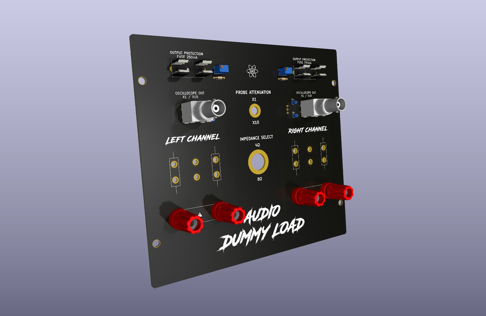
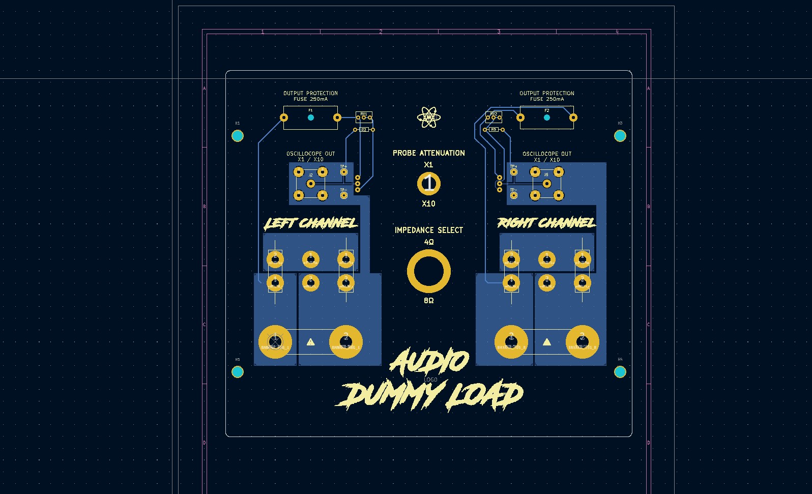
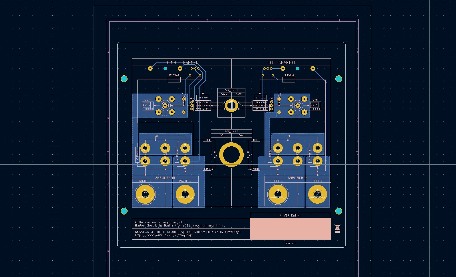
This Audio Speaker Dummy Load lets you test your audio amplifier PCB design in a very convenient way. You can simulate a working condition with the 8/4Ω switch, and you can use BNC connector to the output to monitor it on an Oscilloscope.
An essential piece of equipment for audio enthusiasts, this dummy load amplifier lets you test an entire audio system as it would exist in the real world. The device lets you switch from 4 to 8 ohm loads with a switch on top, and comes with a bnc connector for connecting your oscilloscope for viewing sound pressure.
Design overview
What is NOP instruction?
An 8Ω/4Ω switch enables the different impedance requirement to be met. The dummy load allows you to safely test and measure your amplifier's performance. When loading the test equipment with a dummy load, this will ensure that the amplifier operates as per specifications. For audio amplifier testing, the dummy load presents a resistor network that is equivalent to a complex impedance.
How does it all work?
Lorem Ipsum Dolor sit amet
You can use CPU tester in conjuction with Z80 QFP44 to DIP40 and/or PLCC44 to DIP40 adaptors.
These boards look absolutely gorgeous in standard blue solder mask because hey! Zilog was all about blue! All components in BOM are standard offshelf parts with no special lead time. I bought mine on Ali.
┌( ͝° ͜ʖ͡°)=ε/̵͇̿̿/’̿’̿ ̿
Except where otherwise noted, content on this site is licensed under a Creative Commons Attribution 4.0 International license. CC-BY-4.0
I have created content on this website free to use for personal, educational and commercial purposes. If you like or use my work, please mention me or perhaps consider a donation.
| or |
... but if you feel like getting something for nothing isn't your cup of tea (completely understandable) (ಥ﹏ಥ) and a prefer to support me and get something back in return, then you can purchase directly on my eBay or Tindie shop. However if you are still up for an adventure */in very positive way/* (and are happy to have PCB's made yourself in your favourite PCB house - PCBWay is highly recommended), then carry on, download gerber files and have fun! ( ͡° ͜ʖ ͡°)


EDA preview
click on pictures to enlarge
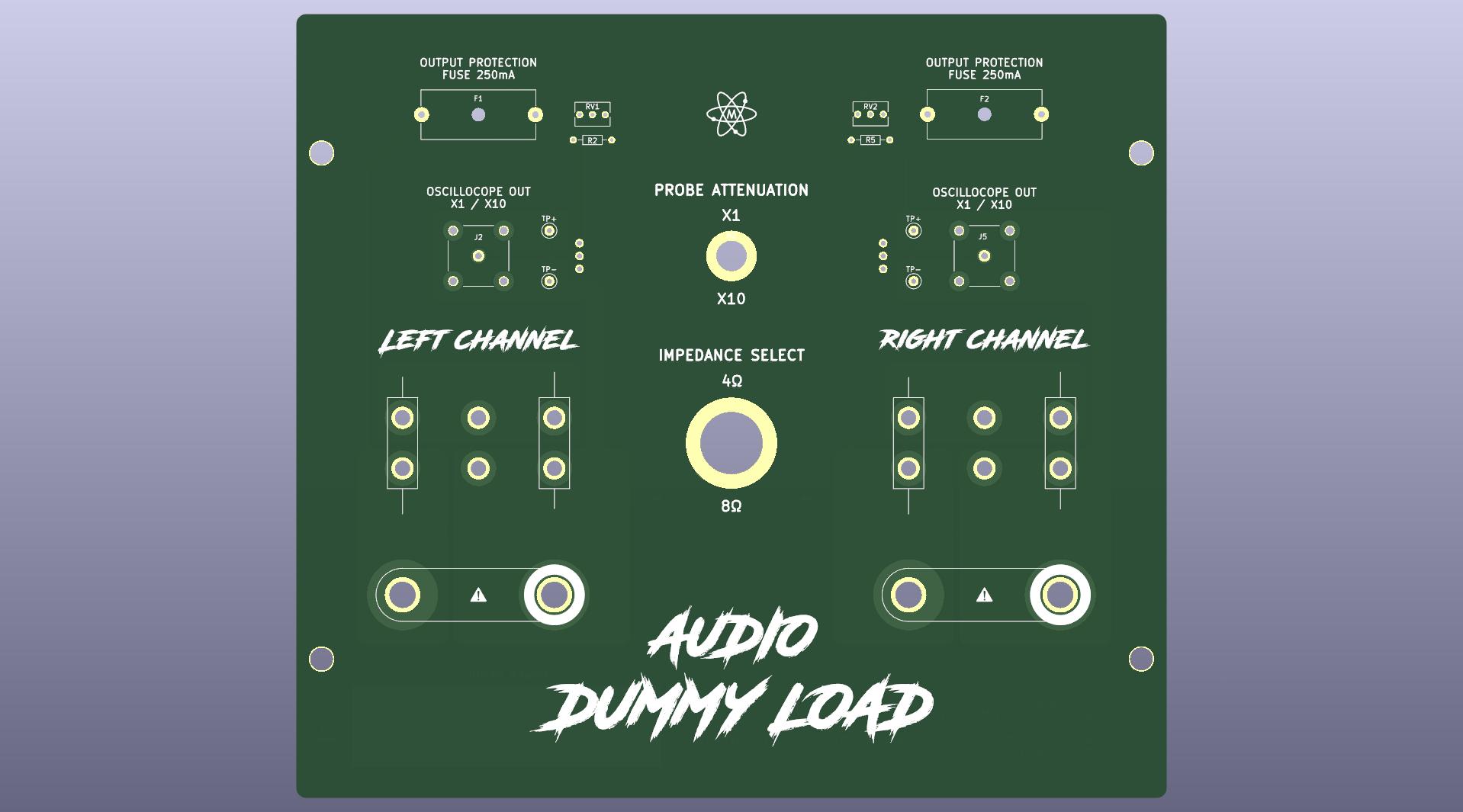
3d render v1.2
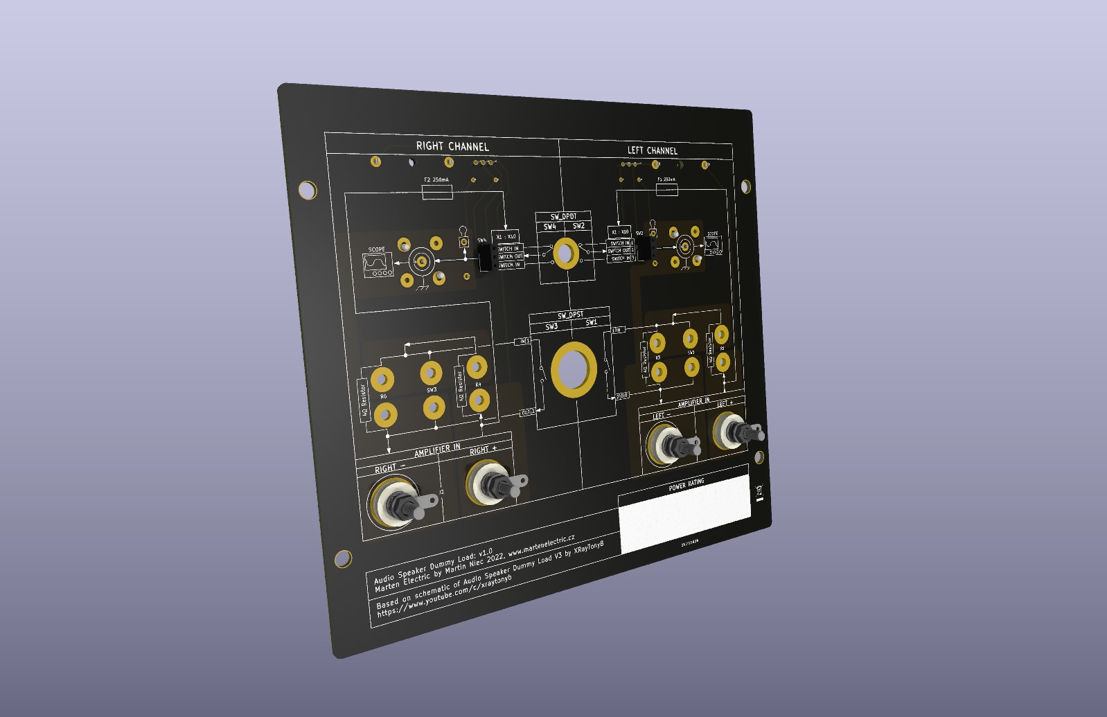
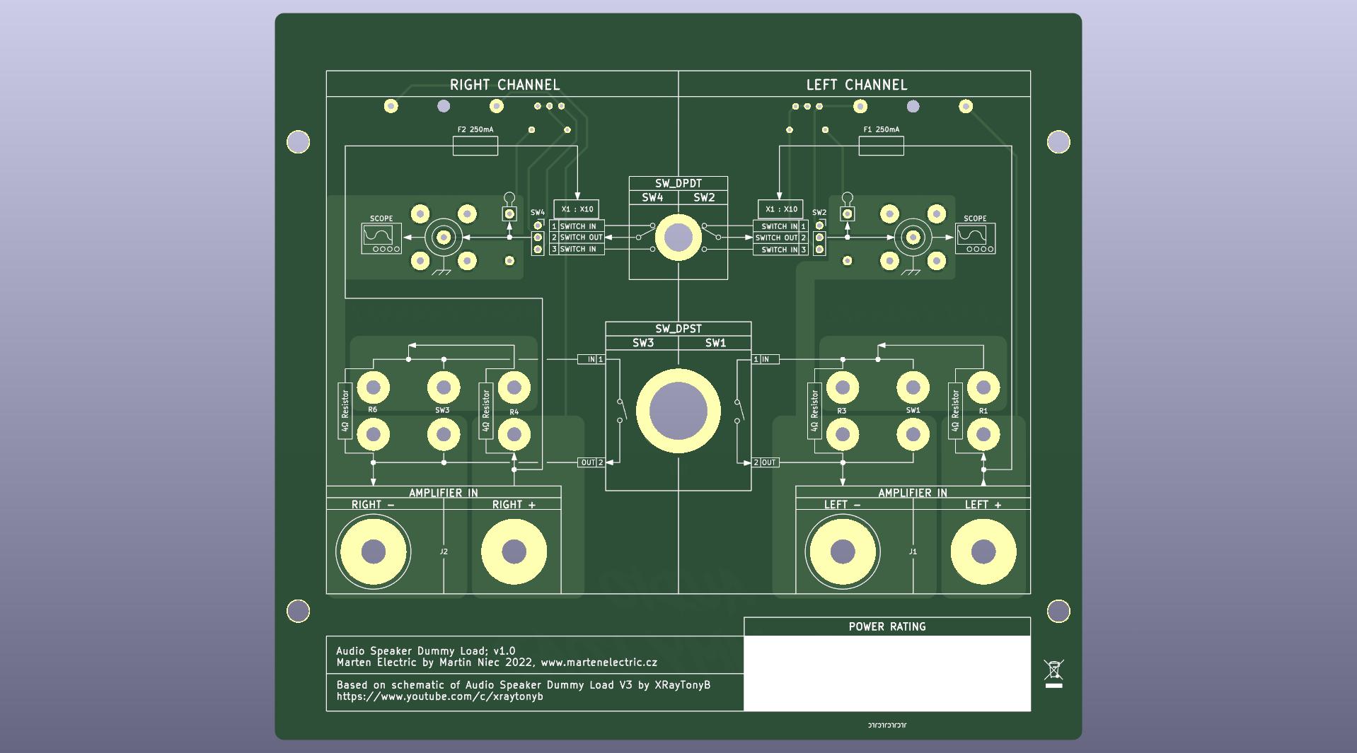
PCB design layout
Specifications
Board Type: Tester
Board Material: FR4-Standard Tg 130-140C Epoxy Glass Composite
Layers: Double sided
PCB Colour: Black colour solder mask, white silk screen lettering
Surface Finish: Lead free HASL-RoHS
External size (assembled): 172 x 155 x 15.0 mm
Board Thickness: standard 1.6mm
Copper Thickness: 35um
PCB weight: 10g
Asembled weight: 47g
Bill of materials
| Reference | Value | Footprint | Qty | Notes |
|---|---|---|---|---|
| Printed Circuit Board | PCB 172 x 155 mm, M4 mounting holes | 1 | v1.2 | |
| LED PWR | Green | LED_THT:LED_D3.0mm | 1 | |
| LED A0-A7 | Red | LED_THT:LED_D3.0mm | 8 | |
| LED M1-WR | Orange | LED_THT:LED_D3.0mm | 5 | |
| LED CLK | Yellow | LED_THT:LED_D3.0mm | 1 | |
| C1 | 100nF | Capacitor_THT:C_Disc_D4.3mm_W1.9mm_P5.00mm | 1 | |
| C2 | 10uF | Capacitor_THT:CP_Radial_D5.0mm_P2.50mm | 1 | |
| C3 | 10nF | Capacitor_THT:C_Disc_D4.3mm_W1.9mm_P5.00mm | 1 | |
| C4 | 1uF | Capacitor_THT:CP_Radial_D5.0mm_P2.50mm | 1 | |
| R1-R14,R18,R29,R31 | 1K | Resistor_THT:R_Axial_DIN0207_L6.3mm_D2.5mm_P7.62mm_Horizontal | 17 | |
| R15-R17,R19-R28,R30 | 10K | Resistor_THT:R_Axial_DIN0207_L6.3mm_D2.5mm_P7.62mm_Horizontal | 14 | |
| Q1 | 2N222 | Package_TO_SOT_THT:TO-92_Inline | 1 | NPN Transistor, Alternative 2N3904 |
| SW1 | Reset | Button_Switch_THT:SW_PUSH_6mm_H5mm | 1 | Momentary Push Button Switch |
| RV1 | 500K / 504 | Potentiometer_THT:Potentiometer_ACP_CA9-H5_Horizontal | 1 | Frequency adjust |
Assembly instructions and notes
■ Gerber files contain " JLCJLCJLCJLC" to the silk layer. You can specify a location of the order number, select the "Specify a location" option when you place an order. Only if you order via JLCPCB
■ Use a temperature-controlled soldering station and quality solder, use plenty of flux. Take care not to leave solder bridges as any short circuit will most likely lead to failures
■ Use a temperature-controlled heat gun station and quality solder paste, use plenty of flux. Take care not to leave solder bridges as any short circuit will most likely lead to failures
■ Use quality ZIF Socket for CPU, alternative machined socket with golden plated pin headers is recommended, they are rather cheap and will protect your precious DIP socket. 555 timer can be soldered directly, however little DIP8 socket is recommended.
■ Use little screwdriver to adjust frequency of 555 Timer
■ Assembly:
1 - First start with USB B connector: Hold socket in place and dab a bit of solder on the little connector, it's fiddly due to the nature and size of SMD components so you might want to use a solder wick if you overdo it. Test for solder bridges just in case. Alternatively use solder paste and hot air.
2 - Start from the physically lowest component: Resistors, caps, LEDs, transistor, button etc. Solder ZIF socket as a last component.
3 - Clean the flux residue and crap with IPA
4 - Test for voltages prior to first use, just in case... because the last thing you want is to fry your CPU
5 - Insert CPU, plug in USB power plug and Enjoy!
■ How to test the CPU:
1 - Slot the Zilog Z80 CPU into the ZIF socket. CPU should fall into the ZIF socket without force.
2 - Please Make sure the Z80 is inserted correctly. Pin 1 CPU is top left by the lever.
3 - Power up the CPU tester by inserting a Mini USB Type B cable from the PC or use standard +5VDC USB phone charger.
4 - Press Reset button. CPU starts from zero count state.
5 - Fiddle with the potentiometer to achieve the clock speed you require for your experiments.
6 - Enjoy!
Schematic
| File type | File name | File size | Last modified |
|---|---|---|---|
| Audio Speaker Dummy Load Schematic v1.0 |  schematic_audio_speaker_dummy_load_v11.pdf |
84 kB | 19/09/2021 |
Design Files
| File type | File name | File size | Last modified |
|---|---|---|---|
| PCB layers v1.0 | pcblayers__audio_speaker_dummy_load_v121.pdf |
199 kB | 19/08/2022 |
| BOM and Component placement v1.0 | bom_component_placement__audio_speaker_dummy_load_v12.pdf |
166 kB | 04/06/2022 |
| Component placement v1.0 | component_placement__audio_speaker_dummy_load_v12.pdf |
25 kB | 03/06/2022 |
| Gerbers 172 x 155 mm, 2 Layer FR4, v1.0 |  gerbers_z80cpu_tester_v121.zip |
127 kB | 19/08/2022 |
| Solder paste stencil | Not available for this project | - | - |
Photographs
click on pictures to enlarge
gerber files and photographs may vary, v1.0 pictured


Versions and revisions
This section lists the project version and revision history. v1.0
■ prototype